



Pipe (Tubular)Conveyor Belt
General Introduction:
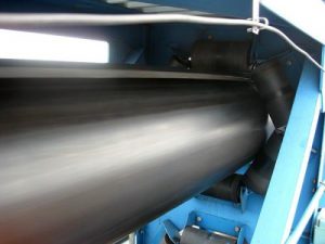
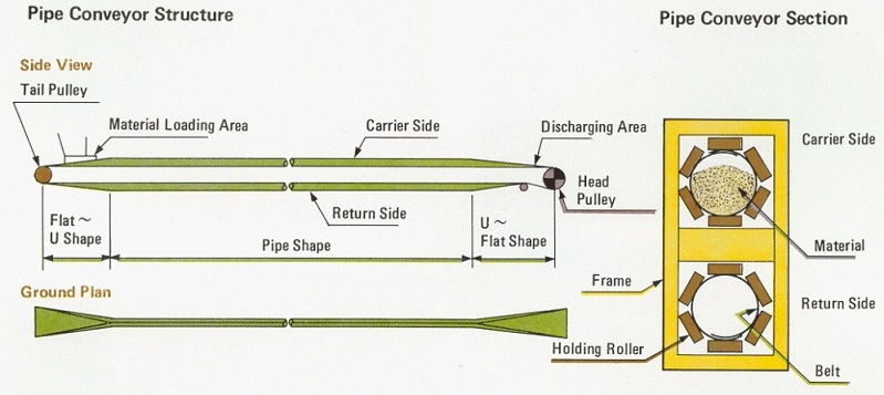
Pipe conveyor belt (also called tubular conveyor belt)is used to support the pipe belt conveyor, with the help of external force in the whole transportation line or part of the transportation line of the conveyor belt into a tubular shape. Pipe conveyor belt use the high tenacity EP fabric or steel cord as the core of carcass, using the high strength, high abrasion resistant rubber as top and bottom cover, the belt will change from plane to U shape on operation, and finally rolled into a tube for enclosed conveying.
Technical Characteristics:
1. Moderate rigidity for tubing and bend easily, with the ability to maintain stability of the roundness.Pipe conveyor belts can be bent horizontally, vertically or diagonally, making them suitable for complex layouts and limited-space environments. This makes it possible to implement more flexible transmission lines within limited space.
2. The sealing is good at the overlap edge, fatigue resistance, abrasion resistance, with stable bearing capacity.
3. As enclosed conveying, the materials won’t float in the sky or fall, and will not affect the environment, especially for the fine materials such as powder or paste.
4. To protect the material from wind, rain, snow and some other environment.
5. Compared with traditional flat conveyor belts, pipe conveyor belts consume less energy during transportation. This is because the tubular structure can reduce the resistance and friction of the material and reduce the energy required for transportation.
The width of belt and corresponding pipe diameter specifications (Unit: mm)
Nominal pipe dia.(mm) | Width (mm) | Size of overlap(mm) | Actual pipe dia.(mm) | Loading area at 70%(mm) | Capability at speed 2m/s(m3/h) | Lump size (Max.) |
100 | 430 | 115 | 100.27 | 0.005 | 40 | 40 |
150 | 600 | 129 | 143.24 | 0.011 | 81 | 80 |
200 | 780 | 122 | 186.21 | 0.019 | 137 | 100 |
250 | 900 | 215 | 279.18 | 0.028 | 208 | 130 |
300 | 1050 | 158 | 286.48 | 0.045 | 325 | 150 |
350 | 1300 | 201 | 343.77 | 0.064 | 468 | 180 |
400 | 1600 | 244 | 401.07 | 0.088 | 637 | 200 |
450 | 1650 | 237 | 458.37 | 0.115 | 832 | 220 |
500 | 1900 | 330 | 507.5 | 0.145 | 850 | 230 |
600 | 2250 | 366 | 609 | 0.205 | 1020 | 250 |
The Top 5 Rubber Conveyor Belt Manufactures In China 2026
How to choose crushing plant conveyor belt for 100 ~ 1000T/H scale?
EP conveyor belt layer is the more the better?
How to choose the cover thickness of conveyor belt?
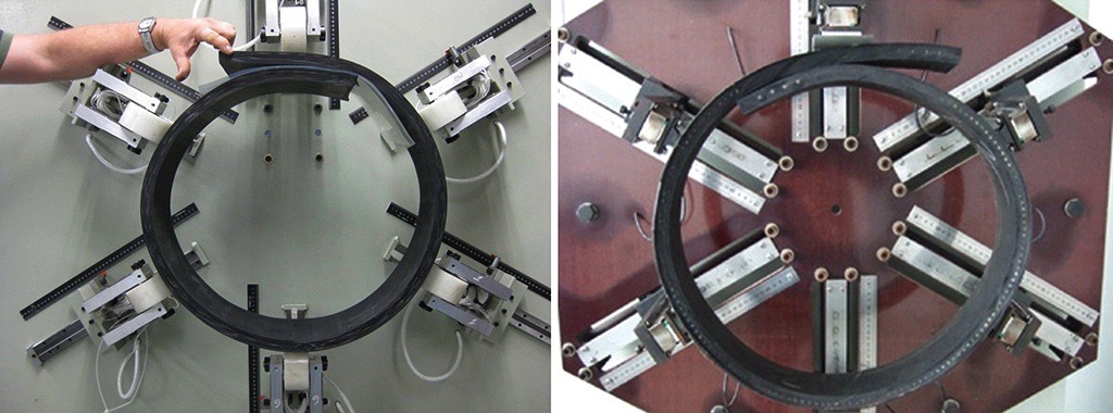
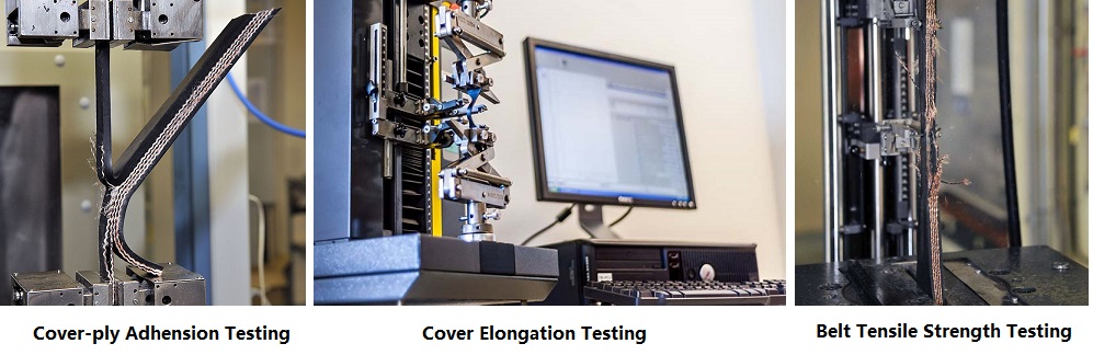
Due to the unique structure and applications of pipe conveyors, they require higher technical specifications compared to conventional conveyor belts. For example, the requirements for EP (ethylene propylene) and NN (nylon) fabrics include enhanced flexibility in the latitudinal direction, thicker skim rubber, and stronger adhesion between fabrics and cover. Consequently, the production of pipe conveyors imposes greater demands on conveyor belt manufacturers’ capabilities, necessitating them to possess stringent production management and quality testing capabilities.
Pipe Rubber Cover Grade:
| Cover Grade | Country | Applicable Standards | Min.Tensile Strength(Mpa) | Min.Elongation at Break(%) | Max.Abrasion Loss(mm3) |
| DIN-Z | Germany | DIN22102 | 15 | 350 | 250 |
| DIN-Y | Germany | DIN22102 | 20 | 400 | 150 |
| DIN-X | Germany | DIN22102 | 25 | 450 | 120 |
| DIN-W | Germany | DIN22102 | 18 | 400 | 90 |
| RMA-I | U.S.A | RMA | 17 | 400 | 150 |
| RMA-II | U.S.A | RMA | 14 | 400 | 200 |
| ARPM RMA-I | U.S.A | ARPM | 17 | 400 | 125 |
| ARPM RMA-II | U.S.A | ARPM | 14 | 400 | 175 |
| ISO-L | International | ISO -10247 | 15 | 350 | 200 |
| ISO-H | International | ISO -10247 | 24 | 450 | 120 |
| ISO-D | International | ISO -10247 | 18 | 400 | 100 |
| AS-N | Australian | AS -1332 | 17 | 400 | 200 |
| AS-M | Australian | AS -1332 | 24 | 450 | 125 |
| AS-A | Australian | AS -1332 | 17 | 400 | 70 |
| SANS-N | South Africa | SANS-1173 | 17 | 400 | 150 |
| SANS-M | South Africa | SANS-1173 | 25 | 450 | 120 |
| SANS-A | South Africa | SANS-1173 | 18 | 400 | 70 |
| BS-M | UK | BS-490 | 24 | 450 | 120 |
| BS-N | UK | BS-490 | 17 | 400 | 200 |
| IS-N-17 | India | IS 1891 | 17 | 400 | 200 |
| IS-M-24 | India | IS 1891 | 24 | 450 | 150 |
| JIS-G | Japan | JIS-K 6332 | 14 | 400 | 250 |
| JIS-L | Japan | JIS-K 6332 | 15 | 350 | 200 |
| JIS-D | Japan | JIS-K 6332 | 18 | 400 | 100 |
| JIS-H | Japan | JIS-K 6332 | 24 | 450 | 120 |
| GB-H | China | GB/T 7984 | 24 | 450 | 120 |
| GB-D | China | GB/T 7984 | 18 | 400 | 100 |
| GB-L | China | GB/T 7984 | 15 | 350 | 200 |
10 Technical FAQs About Pipe Conveyor Belts for Enclosed Bulk Material Handling
1.What is a Pipe Conveyor Belt, and how does it transition from a flat belt to a closed pipe structure?
A Pipe Conveyor Belt is a specialized, enclosed bulk material handling technology designed to provide continuous, dust-free, and spillage-free transport over complex overland or plant routes.
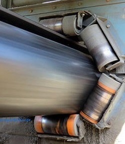
The conveying cycle functions through a distinct spatial deformation sequence: Loading Zone: The belt enters the tail section in a standard flat or shallow troughed configuration (typically supported by 3-roll troughing idlers) where bulk material is fed into the center. Transition Zone: Over a calculated transition distance, hexagonal finger-idler sets progressively fold the belt edges inward, causing the belt to overlap its two edges to form a closed, tubular pipe cross-section. Tubular Strand: The belt maintains this continuous tubular shape along both the carrying and return strands, held firmly in place by six-sided hexagonal idler panels. Discharge Zone: As the belt approaches the drive head or discharge pulley, the process reverses: the hexagonal idler set gradually unrolls the belt back into a flat profile to discharge the payload cleanly over the head pulley.
2.What are the primary advantages of a Pipe Conveyor Belt over conventional troughed belt conveyors?
Pipe conveyor systems solve critical environmental, space, and terrain constraints that limit conventional open belt designs: Zero Environmental Contamination & Spillage: The overlapping tubular seal completely encloses the material, eliminating windborne dust losses, rainwater infiltration, and spillage along the entire overland route. Tight Spatial Radii & 3D Bending: Pipe belts can negotiate horizontal and vertical curves with radii as tight as 300 to 600 times the pipe diameter (D). This eliminates the need for expensive intermediate transfer towers. Steep Incline Capability: The internal compression exerted by the overlapping belt circumference generates extra internal friction, enabling conveying angles up to 28° ~ 30° (compared to 15° ~ 18° for standard flat belts). Enclosed Return Strand: The empty return strand is also closed into a pipe shape, trapping residual material dust inside the tube and preventing spillage underneath the return structure.
3.How do I calculate the correct Pipe Diameter (D) and effective cross-sectional load area?
Pipe belt diameter selection depends on the maximum material lump size, volumetric throughput, and belt speed. The nominal outer pipe diameter (D) dictates the effective internal load cross-section: Cross-Sectional Area (A) ≈ 0.75 × π × (D/2)² × Cfill (Where Cfill is the volumetric fill factor, typically maintained between 60% and 75%).
| Material Sizing Type | Max. Allowable Lump Size | Recommended Fill Factor (Cfill) | Operating Risk if Exceeded |
|---|---|---|---|
| Homogeneous Granular | ≤ 0.33 × D | 65% ~ 70% | Overfilling (>75%) causes seam popping & idler fatigue |
| Unsorted with Fines | ≤ 0.25 × D | 60% ~ 68% | Large lump jams cause uneven pipe rotation |
| Abrasive / Sticky Clays | ≤ 0.20 × D | 55% ~ 65% | Low fill (<50%) leads to pipe collapse and deformation |
4.What is “Pipe Rotation / Twisting,” and how can it be prevented?
Pipe rotation (twisting) occurs when the longitudinal axis of the pipe shifts off-center, causing the overlapping top seam to rotate sideways toward the 3 o’clock or 9 o’clock idler positions. Left uncorrected, rotation can cause severe edge damage, material leakage, and belt jam-ups at transition zones.
Primary Causes of Rotation: Asymmetrical belt tension distribution across the carcass width. Misalignment or thermal expansion of the hexagonal support idler frames. Off-center loading at the tail feed chute. Uneven belt manufacturing thickness or transverse stiffness variations.
Corrective and Preventive Measures: Adjustable Off-Set Idlers: Tilting the hexagonal guide idlers slightly (1° ~ 2°) in the direction counter to rotation generates a restoring steering force. Self-Aligning Hexagonal Idler Sets: Installing motorized or mechanical self-aligning idler frames that automatically pivot when edge sensors detect rotation. Precise Chute Alignment: Ensuring the load enters symmetrically along the central longitudinal axis of the flat belt section before pipe closure.
5.What unique carcass properties are required for Pipe Conveyor Belts (Transverse Stiffness Balancing)?
A pipe conveyor belt cannot be manufactured using standard flat-belt carcass formulations. It requires a delicate engineering balance between Longitudinal Tensile Flexibility and Transverse Elastic Stiffness.
| Carcass Grade | Construction Detail | Transverse Reinforcement | Best Suited Conveyor Distance |
|---|---|---|---|
| EP Fabric Grade | Multi-ply Polyester/Nylon weave | Dual monofilament fabric layers | Short to medium routes (< 2 km) |
| ST Steel Cord Grade | High-tensile steel cord cables | Upper & lower transverse steel breakers | Long-distance overland routes (> 2 km) |
6.How do I determine the Transition Distance (Lt) from flat to pipe shape?
The transition distance (Lt) is the distance along the conveyor path required to gradually transform the belt from a completely flat profile over the head/tail pulley into a fully sealed pipe shape (or vice versa). Lt ≈ Kt × D (Where D is nominal pipe diameter and Kt is the transition distance factor).
| Belt Carcass Type | Transition Factor (Kt) | Example Radius Calculation (D=300 mm) |
|---|---|---|
| Fabric Carcass (EP) | 25 ~ 30 | Lt = 25 × 0.30 m = 7.5 meters |
| Steel Cord Carcass (ST) | 50 ~ 60 | Lt = 50 × 0.30 m = 15.0 meters |
7.What overlapping seam width is required to ensure a dust-tight seal?
The overlapping seam section at the top of the pipe profile is critical to prevent bulk material and fine dust from blowing out during transport or leaking when navigating horizontal curves. Overlap Width (Wo) ≈ 0.5 ~ 0.75 × D
| Pipe Diameter (D) | Overlap Ratio (Wo) | Standard Flat Belt Width Required (B) | Material Application |
|---|---|---|---|
| 150 mm | 0.60 × D = 90 mm | 560 mm | Fine chemical powder, grain |
| 200 mm | 0.60 × D = 120 mm | 750 mm | Fly ash, fine coal dust, cement raw meal |
| 300 mm | 0.60 × D = 180 mm | 1150 mm ~ 1200 mm | Crushed limestone, iron ore fines, copper concentrate |
| 400 mm | 0.65 × D = 260 mm | 1500 mm ~ 1600 mm | Run-of-mine coal, primary quarry aggregate |
8.How are horizontal and vertical curves engineered for pipe conveyors?
Pipe conveyors navigate three-dimensional terrain curves by utilizing the structural confinement of the six surrounding hexagonal idler rollers.
Minimum Terrain Bending Radii Limits (Rmin):
| Carcass Type | Minimum Horizontal Curve Radius | Minimum Vertical Curve Radius |
|---|---|---|
| Fabric Carcass Belts (EP Series) | Rmin ≥ 300 × D | Rmin ≥ 300 × D |
| Steel Cord Carcass Belts (ST Series) | Rmin ≥ 600 × D | Rmin ≥ 600 × D |
9.What specialized splicing methods are required for Pipe Conveyor Belts?
Pipe conveyor splices undergo dynamic multi-axial bending forces (simultaneous longitudinal tension and repeated transverse flex fatigue). Splicing methods must preserve both structural strength and cross-sectional flexibility: Hot Vulcanized Splicing (Mandatory): Cold bonding and mechanical fasteners are unsuitable for pipe belts due to the extreme fatigue stress caused by continuous pipe opening and closing cycles. Bias-Cut Angle Preparation: Fabric and steel cord joints are prepared at a 16° ~ 22° bias angle. This spreads the flexural transition across the hexagonal idlers gradually, avoiding sudden stiffness steps. Match-Grade Cover Compound Replacement: Splice tie-gum and top cover rubber must match the exact transverse elasticity grade of the base belt. Overly rigid splice rubber creates a “hard spot” that causes the pipe to pop open or mistrack every time the joint passes through a hexagonal idler set.
10.How should condition monitoring and routine maintenance be performed on pipe conveyor systems?
Maintaining a pipe conveyor system requires monitoring the interaction between the belt structure and the surrounding hexagonal support framework: Overlap Location Tracking: Perform continuous visual or sensor monitoring of the overlap seam position along the conveyor run. Deviation of the seam past the 11 o’clock or 1 o’clock position requires immediate idler offset adjustment. Hexagonal Idler Roller Inspection: Regularly check the bearing condition of all six idlers in each support panel. A seized or damaged roller induces localized friction, scoring the belt cover rubber and forcing the pipe to rotate out of alignment. Transition Zone Edge Stress Inspection: Check the belt edges at the tail and head transition zones for signs of cracking, fraying, or thickness reduction. High edge wear indicates an insufficient transition length (Lt) or improper chute loading. Ultrasonic Cover & Overlap Wear Profiling: Measure cover rubber thickness along the inner and outer overlap zones. Accelerated wear along the overlap edges indicates excessive internal fill levels or abrasive material entrapment inside the seam fold.
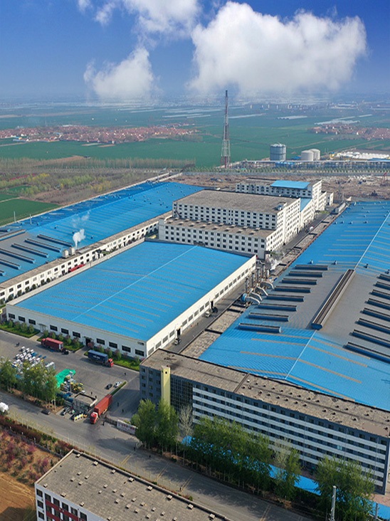
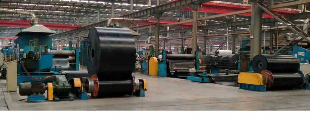
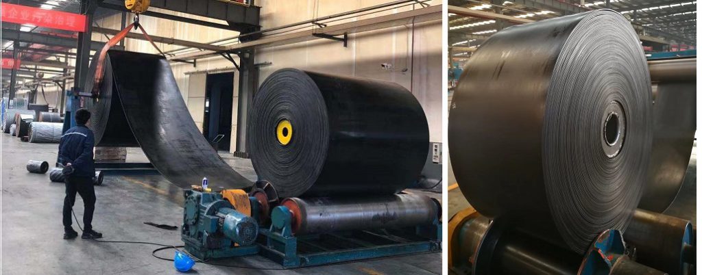
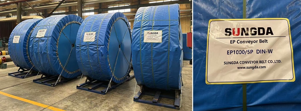
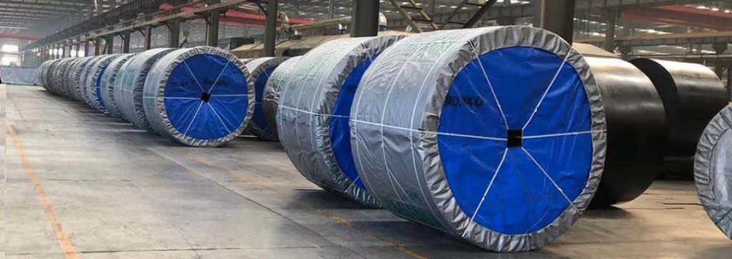
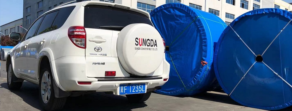
SUNGDA Conveyor Belt Vulcanization Workshop


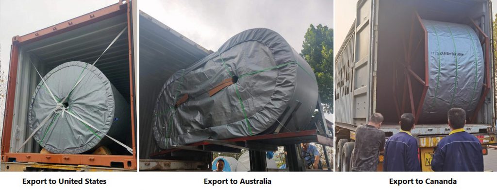
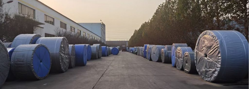

Tags: EP conveyor belt,manufacture,pipe conveyor belt,steel cord,tubular,TUBULAR CONVEYOR BELT
Related Products
-
Material Composition of High-Quality Conveyor Belts (from ContiTech & Dunlop)
No. -
How to Chooe Right Steel Cord Conveyor Belt
No. -
What Are the Tensile Strength and Elongation in Rubber Conveyor Belts?
No. -
What Are the Key Properties of T1, T2, T3, T4 Heat-Resistant Conveyor Belts?
No. -
What’s “kg/cm²” in Conveyor Belt and How Convert it into other Units?
No. -

How to Calculate PIW of Conveyor Belt?
No. -
How to Convert PIW Conveyor belt to EP Belt?
No. -
How to Clean EP Conveyor Belt
No. -
Common causes and solutions for sagging of EP conveyor belts
No. -
What is the reasonable speed of the ep conveyor belt?
No.