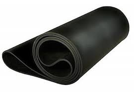
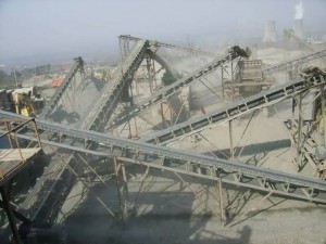
Sidewall Conveyor Belt
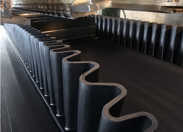
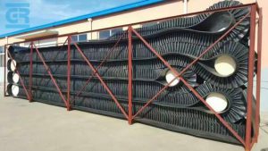
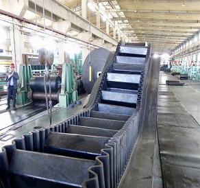
Corrugated sidewall conveyor belt is one of the most effective ways of elevating materials in a confined space,
the economy is achieved by single belt operation, wide range material can be handled, less space requirement,
no transfer point, low maintenance, and big capacity. A corrugated sidewall belt can be designed into a set of complete transportation system according to application.
Feature:
Increase the transporting capacity to 4 times compared to the standard conveyor belt.
Save installation space due to the possibility of increasing the angle of inclination up to 90。
Small pulley diameters may be used, without the need for skirt boards. Facility costs are reduced with flat rollers
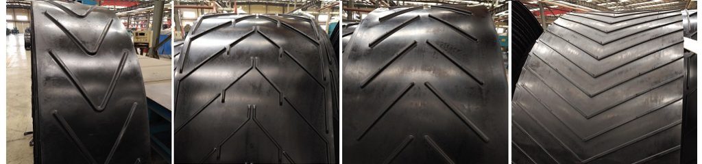
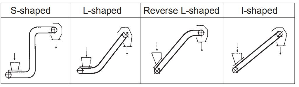
Sidewall major line shapes:
Base Belt Structure:
Reinforced core; Cross rigid.
Sidewall height: 60~500mm
Cleat height: 55~460mm
Belt core: Cotton, Nylon, EP or Steel Cord Belt width: 300~1800mm
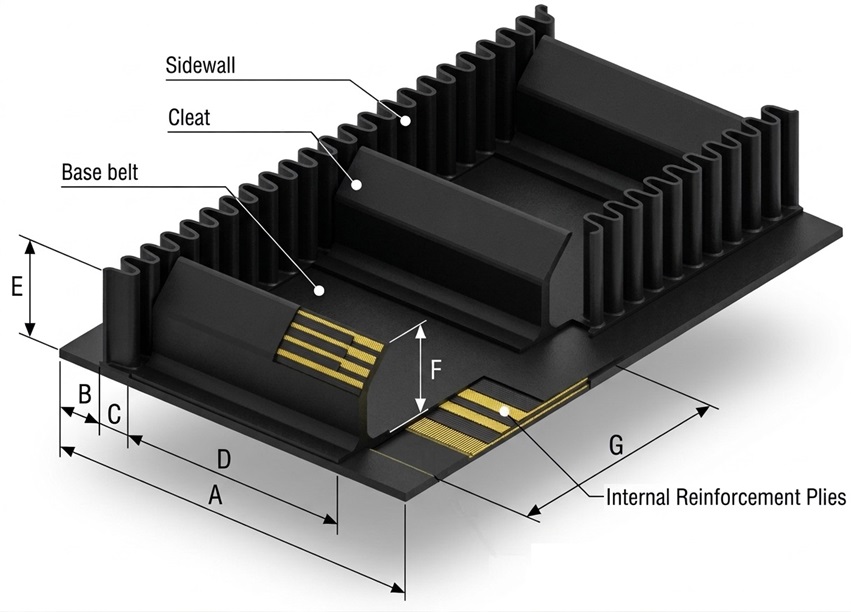
Cleat types:
The cleat is made of enforced fabric, solid, anti-shock to avoid distortion.
“T” cleat are normally used for abrasion condition
“C” cleat are normally used up to 40 degree
“TC” and “TSC” are normally used from 40 degrees to 90 degree
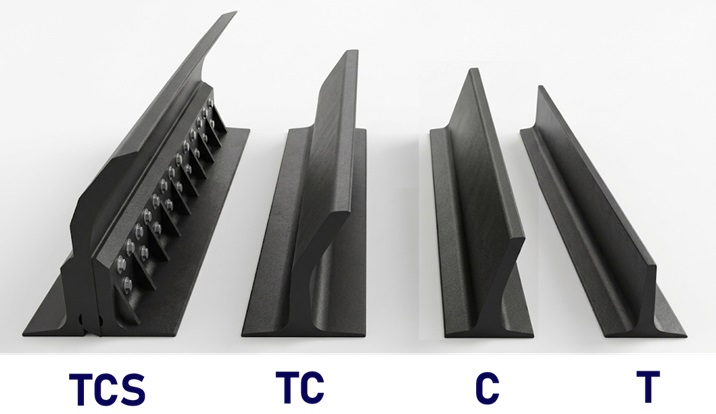
| Cleat Type | Cleat Height (mm) | Sidewall Height (mm) | Bottom Width (mm) | Weight (kg/m) | Minimum Pulley Diameter (mm) |
| C | 90 | 100 | 110 | 2.81 | 250 |
| C | 110 | 120 | 110 | 3.27 | 315 |
| T | 90 | 100 | 110 | 2.70 | 250 |
| T | 110 | 120 | 110 | 3.23 | 315 |
| T | 140 | 160 | 160 | 5.49 | 400 |
| T | 180 | 200 | 160 | 6.67 | 500 |
| T | 230 | 240 | 160 | 8.60 | 630 |
| TC | 90 | 100 | 110 | 3.22 | 250 |
| TC | 110 | 120 | 110 | 3.94 | 315 |
| TC | 140 | 160 | 150 | 5.49 | 400 |
| TC | 180 | 200 | 150 | 6.81 | 500 |
| TC | 230 | 240 | 160 | 8.68 | 630 |
| TC | 280 | 300 | 180 | 14.90 | 800 |
| TCS | 230 | 240 | 160 | 13.80 | 630 |
| TCS | 280 | 300 | 160 | 15.30 | 800 |
| TCS | 360 | 400 | 230 | 22.80 | 1000 |
| TCS | 470 | 500 | 230 | 30.80 | 1250 |
Sidewall type:
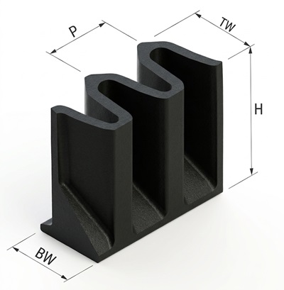
| Sidewall Height (H) | Wave Crest Width (TW) | Wave Base Width (BW) | Wave Spacing (P) | Weight (kg/m) |
| 100 | 44 | 50 | 42 | 2.34 |
| 120 | 44 | 50 | 42 | 2.78 |
| 160 | 66 | 75 | 63 | 4.42 |
| 200 | 66 | 75 | 63 | 5.82 |
| 240 | 66 | 75 | 63 | 8.49 |
| 300 | 88 | 100 | 84 | 12.48 |
| 400 | 88 | 100 | 84 | 17.60 |
| 500 | 110 | 125 | 105 | 24.40 |
| 630 | 110 | 125 | 105 | 31.50 |
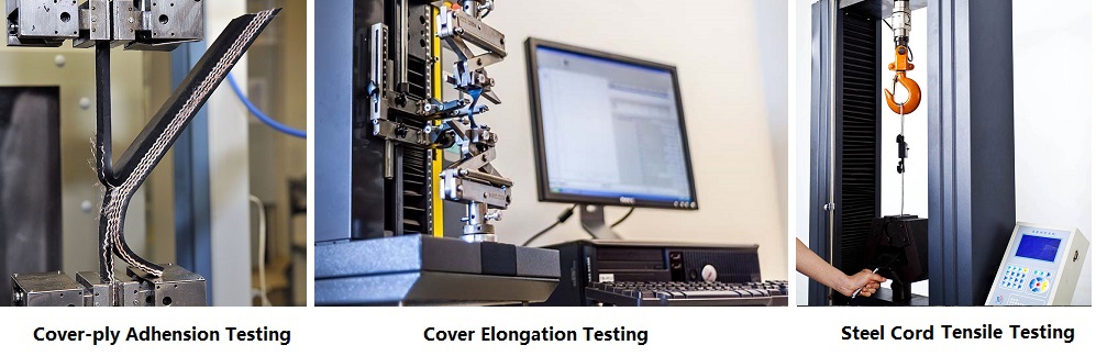
SUNGDA utilizes a specially formulated rubber compound that combines exceptional flexibility with high abrasion resistance and tensile strength, delivering outstanding resistance to flexing and dynamic fatigue. To effectively prevent structural cracking, SUNGDA incorporates heavy-duty fabric reinforcements into the sidewall design. Furthermore, all products undergo rigorous dynamic fatigue testing under European standards to simulate actual field operating conditions, fully ensuring product reliability and long-lasting performance.
SUNGDA’s engineered sidewall profile guarantees maximum flexing capacity without fatigue, while its excellent vertical stability supports heavy loads and smooth return-side operation. Featuring a diagonal fabric insertion, the sidewalls offer superior tear resistance and enhanced bending flexibility around small radii under high compression.
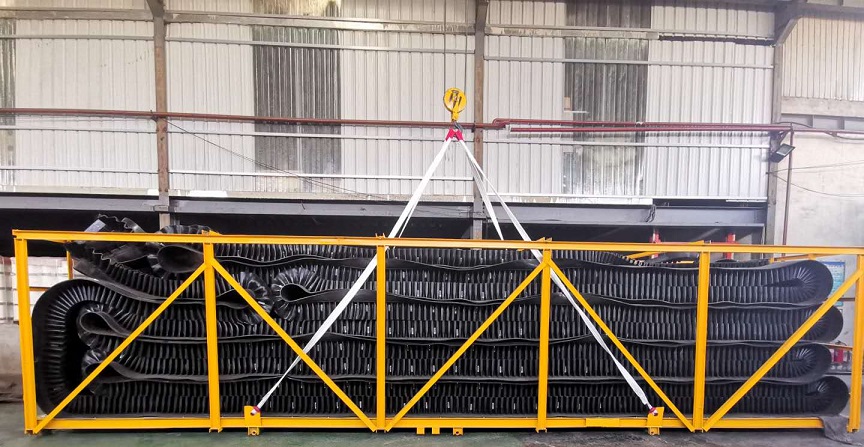
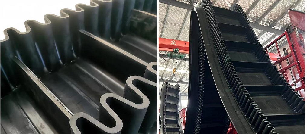
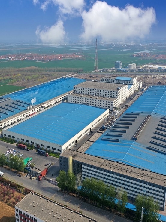
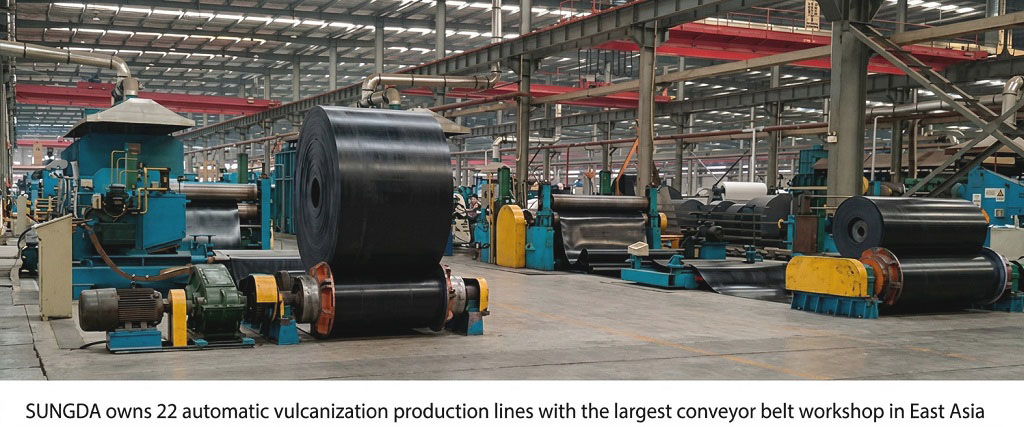
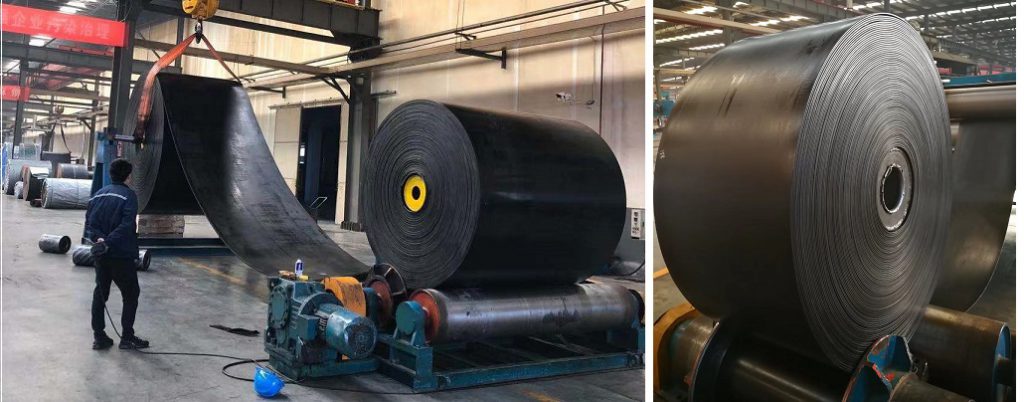
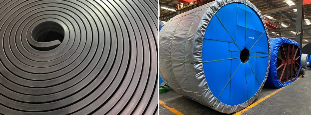
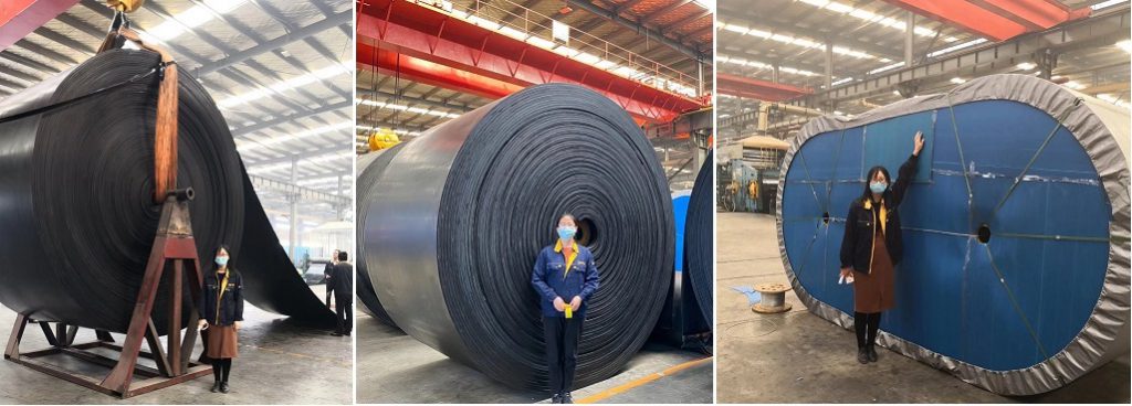
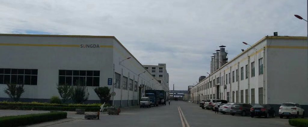
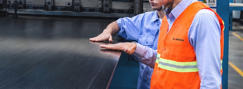
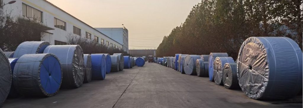
Sungda Conveyor Belt Vulcanization Workshops
10 Technical FAQs About Sidewall Conveyor Belts for Steep-Incline & Vertical Conveying
1.What is a Sidewall Conveyor Belt, and how does it achieve vertical (90°) material conveying?
A Sidewall Conveyor Belt (often called a Pocket or Corrugated Sidewall Belt) is a specialized material handling solution designed to transport bulk materials at extreme incline angles—ranging from 30° up to a vertical 90°—without material spillage.
The belt consists of three integrally vulcanized components that create a continuous moving bucket or pocket system: Cross-Rigid Base Belt: Provides longitudinal flexibility to navigate drive pulleys while imparting extreme transverse rigidity to resist buckling under load. Corrugated Sidewalls: Flexible vertical barriers bonded to both edges of the belt that contain the material laterally while flexing smoothly around drive and bend pulleys. Transverse Cleats: Cross-bars fixed between the corrugated sidewalls that lift and support the material vertically against gravity.
Unlike standard flat or Chevron belts, which rely solely on friction and are limited to 18° ~ 35° inclines, a sidewall belt mechanically traps material within fully enclosed cross-sections, enabling ultra-compact footprint layouts and eliminating expensive transfer towers.
2.What is a “Cross-Rigid” Base Belt, and why is standard EP fabric unsuitable for sidewall systems?
A common engineering failure in vertical conveyor design is installing a standard multi-ply EP fabric belt as the base belt for a corrugated sidewall system.
Under heavy vertical loading, a conveyor belt experiences severe transverse bending forces across its width, particularly when navigating transition curves (from horizontal to vertical) and when supported only on its outer margins by stub idlers or edge rollers.
Standard EP Base Belts vs. Cross-Rigid Base Belts: Standard EP Belts: Exhibit high longitudinal strength but low transverse stiffness. When fitted with heavy sidewalls and cleats, a standard EP belt bows across its width (cupping effect). This cupping compresses the corrugated sidewalls inward, causing wall distortion, joint fatigue, and rapid tearing at the sidewall-to-base bond. Cross-Rigid Base Belts (XE / XST Construction): Feature specialized transverse reinforcement layers—such as high-tensile monofilament synthetic fabrics or transverse steel cord layers—embedded above and below the main longitudinal carcass.
Typical Base Belt Cross-Rigid Design Classifications:
| Base Belt Type | Carcass Construction | Transverse Reinforcement | Best Suited For |
|---|---|---|---|
| XE Grade | Multi-ply EP fabric | Dual monofilament plies | Light to medium duty (H ≤ 120 mm sidewalls) |
| XE+ST Grade | Fabric tensile plies + Steel cord transverse | High-tensile steel wire mesh | Heavy-duty mining / deep inclines (H ≤ 280 mm sidewalls) |
| XST Grade | Full steel cord longitudinal | High-rigidity steel transverse cords | Ultra-heavy duty, high-lift vertical handling (>50 m lift) |
3.How do I select the correct Sidewall Height (H) and Cleat Height (h)?
Determining sidewall and cleat dimensions requires calculating two parameters: Maximum Material Lump Size and Required Volumetric Throughput (V).
To prevent material from overflowing or jamming between the cleat top and the sidewall crest, the sidewall height (H) must always be specified higher than the cleat height (h):
H = h + (10 mm ~ 20 mm)
Selection Guidelines Based on Lump Size and Conveying Angle:
| Incline Angle | Sidewall Height (H) | Cleat Profile Type | Max. Allowable Lump Size | Typical Conveyed Material |
|---|---|---|---|---|
| 30° ~ 45° | 60 mm ~ 120 mm | Straight (T-Type) | <30 mm | Fine sand, grain, small gravel, cement |
| 45° ~ 75° | 120 mm ~ 200 mm | Inclined / Scooped (C-Type) | 30 mm ~ 80 mm | Crushed limestone, coal, fertilizer, slag |
| 75° ~ 90° | 200 mm ~ 400 mm | Deep Scoop / Box (TC-Type) | 80 mm ~ 150 mm+ | Heavy iron ore, primary crusher rock, copper ore |
Engineering Rule: The effective pocket width (distance between internal sidewall bases) should be at least 2.5 to 3.0 times the maximum material lump size to prevent mechanical bridging inside the pocket.
4.T-Type, C-Type, vs. TC-Type Cleats: What are their structural differences and applications?
Transverse cleats serve as the pocket bottom in vertical handling. Selecting the correct cleat geometry dictates discharge efficiency and structural load capacity:
T-Type (Straight Vertical Cleats): Simple vertical rubber profiles. Recommended only for mild inclines (≤ 40°) or free-flowing fine materials. They provide minimal scooping capability at steep angles.
C-Type (Inclined / Curved Cleats): Features an angled top lip that forms a “bucket” or scoop profile. The forward angle carries bulk material at steep inclines (40° ~ 75°) with higher volumetric efficiency while ensuring clean gravity discharge over the head pulley.
TC-Type (Heavy-Duty Scoop Cleats with Reinforcement): Designed for extreme inclines (75° ~ 90°) handling heavy ores and large lump materials. TC-type cleats feature a curved scoop geometry reinforced with internal high-tensile fabric matrix or diagonal rubber struts to prevent the cleat face from bending backward under heavy loads.
5.Why is Hot Vulcanized Bonding mandatory for high-performance sidewalls and cleats?
The bond line where the corrugated sidewall and transverse cleats join the base belt is subjected to continuous dynamic flexural stress, shear forces, and material impact:
Cold-Bonded Attachment (Glued afterwards): Sidewalls and cleats are glued onto a smooth base belt using two-part room-temperature adhesives. Cold bonding exhibits low initial shear strength, poor resistance to humidity and heat, and is highly prone to peeling and delamination under heavy vertical load or when negotiating deflection wheels.
Hot Vulcanized Attachment (High-Pressure Hot Pressing): The corrugated sidewalls, cleats, and base belt cover rubber are fused together simultaneously in high-pressure vulcanizing presses. The raw rubber matrices interlock at the molecular level, creating a homogenous physical bond.
Procurement Guideline: Always specify 100% Hot Vulcanized Sidewalls and Cleats (with internal fabric reinforcement inside the corrugations) for primary industrial, power generation, and mining installations to guarantee against bond separation.
6.What are Deflection Wheels (Stub Rollers), and how do they affect base belt design?
A defining feature of a “Z-Type” or “S-Type” sidewall conveyor is the transition zone where the belt shifts from a horizontal loading section to a vertical lift strand.
At this transition bend, the belt is pressed downward by Deflection Wheels (also called Stub Rollers or Pressure Wheels) that press exclusively against the flat outer margins (B_M) outside the corrugated sidewalls.
Design Impact on Belt and Conveyor Components: Free Margin Width (B_M): Sufficient flat belt width must be provided outside the corrugated sidewall footprint to allow deflection wheels to roll smoothly without crushing the sidewall corrugations (typically B_M = 50 mm ~ 150 mm per side). High Transverse Bending Stress: As the deflection wheel presses down on the belt edges, the central carrying pocket tries to bulge downward. If the base belt lacks sufficient XE / XST cross-rigidity, the belt will bow transversely, causing the sidewalls to tilt inward and tear at the roots.
7.How do I calculate the minimum drive pulley and bend wheel diameters for sidewall belts?
Determining pulley and wheel dimensions for a corrugated sidewall belt involves checking both the base belt carcass limits and the height of the corrugated sidewalls.
Passing a tall sidewall over a small pulley compresses the inner corrugations while stretching the outer peaks, inducing high fatigue stress at the base bond.
Minimum Drive Pulley & Bend Wheel Sizing Rules: D_min ≥ F_sidewall × H_sidewall (Where H is sidewall height and F is the manufacturer flexibility factor, typically ranging from 2.5 to 4.0).
Recommended Minimum Pulley & Wheel Diameters:
| Sidewall Height (H) | Min. Drive Pulley Diameter (DA) | Min. Inner Bend Wheel Diameter (DB) | Min. Deflection Wheel Diameter (DD) |
|---|---|---|---|
| 80 mm ~ 120 mm | 400 mm | 500 mm | 315 mm |
| 160 mm ~ 200 mm | 630 mm | 800 mm | 500 mm |
| 240 mm ~ 300 mm | 800 mm | 1,000 mm | 630 mm |
| 350 mm ~ 400 mm | 1,000 mm | 1,250 mm | 800 mm |
Procurement Warning: Undersizing bend wheels will cause rapid fatigue cracking at the roots of the corrugated sidewall within the first few months of operation.
8.How is material loading and unloading managed on a 90° vertical sidewall conveyor?
Because sidewall belts operate as open, continuous bucket elevators, loading and discharging require precise chute and speed coordination:
Controlled Feed at Horizontal Section: Material must be fed smoothly onto the flat bottom strand before the belt reaches the vertical deflection curve. Feeding directly onto the vertical incline causes severe material impact, pocket damage, and spillage.
Gentle Acceleration & Troughing: The horizontal feed zone uses impact idlers positioned under the center pocket to support the load while flat stub rollers support the margins.
Inertial & Gravity Discharge: As the belt travels over the head drive pulley at the top of the vertical lift, material is cast outward by a combination of centrifugal force and gravity. For sticky or fine materials, beater wheels, air blast nozzles, or mechanical drop hammers are installed behind the head pulley to knock trapped material out of the deep pockets.
9.How are sidewall conveyor belts spliced on-site?
Splicing a corrugated sidewall belt requires specialized multi-step field vulcanization or mechanical joining techniques because the joint must carry tensile load while accommodating sidewall continuity:
Base Belt Jointing: The cross-rigid base belt carcass is prepared first using standard bias step-lapping (for EP plies) or cord structural layout (for steel cords). The joint is vulcanized using a heated vulcanizing press to restore 85%–90% of nominal carcass strength.
Sidewall & Cleat Splicing: After the base belt joint is cured, matching sections of corrugated sidewall and cleats are spliced across the joint line using specialized cold-bonding adhesives or localized hot-curing matrix blocks. The corrugations across the splice must be precisely aligned to maintain flexibility when passing over deflection wheels.
Mechanical Fastener Pin Joints: Used primarily for quick installation or emergency repairs in underground mining, though mechanical joints reduce overall belt life and allow fine material leakage.
10.What are the key maintenance procedures and condition monitoring standards for sidewall belts?
Because sidewall conveyor systems feature high material lifts within tight structural enclosures, proactive condition monitoring is essential to prevent catastrophic jams:
Sidewall Root Tear Inspection: Perform daily visual or optical camera checks at the internal and external roots of the corrugated sidewalls. Cracks forming at the base bond indicate undersized deflection wheels or excessive transverse belt flexing.
Cleat Tilt & Strut Deformation Checks: Inspect C-type and TC-type cleats for rearward deflection or cracking at the attachment feet. Permanent cleat tilt reduces effective pocket volume and causes material rollback.
Deflection Wheel & Stub Roller Bearing Monitoring: Monitor vibration and temperature on all edge deflection wheels and transition stub rollers. A seized or misaligned deflection roller will wear through the flat outer belt margin (B_M) and destroy the outer sidewall wall within hours.
Pocket Buildup Removal: Regularly inspect and clean sticky material buildup inside the deep pocket corners. Accumulated dead weight increases total drive tension and reduces effective volumetric payload.
The Top 5 Rubber Conveyor Belt Manufactures In China 2026
How to choose crushing plant conveyor belt for 100 ~ 1000T/H scale?
EP conveyor belt layer is the more the better?
How to choose the cover thickness of conveyor belt?

Tags: corrugated,Corrugated sidewall conveyor belt,Elevating conveyor belt,sidewall,sidewall conveyor belt,vertical conveyor belt